This page is applicable to CXB's produced from October 2013. For the "original" CXB design available in limited numbers prior to October 2013, refer to earlier Construction Tips.
Removing Support Structures
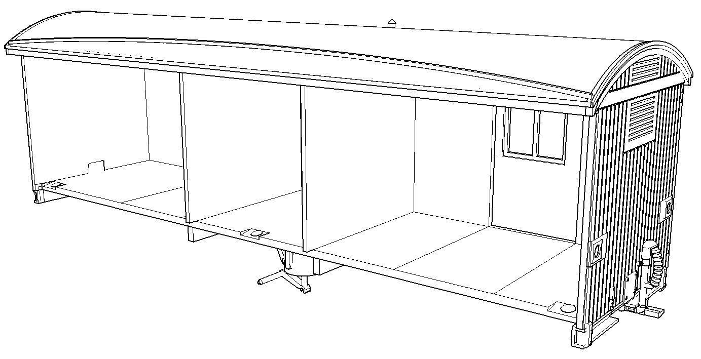
Carefully remove the support structure from both parts of the wagon. It is suggested to use a sharp knife carefully cut the supports away from the roof, ends, and the underframe. Take particular care around the brake handle, brake hoses, W-irons, brake shoes and remainder of brake rigging, and the shunters steps. The end of the brake handle and the shunters' step have a "sacrificial" guard to reduce the risk of breakage during production and shipping. You may wish to leave the guards in place until the majority of the assembly work has been complete to minimise the risk of breakage.
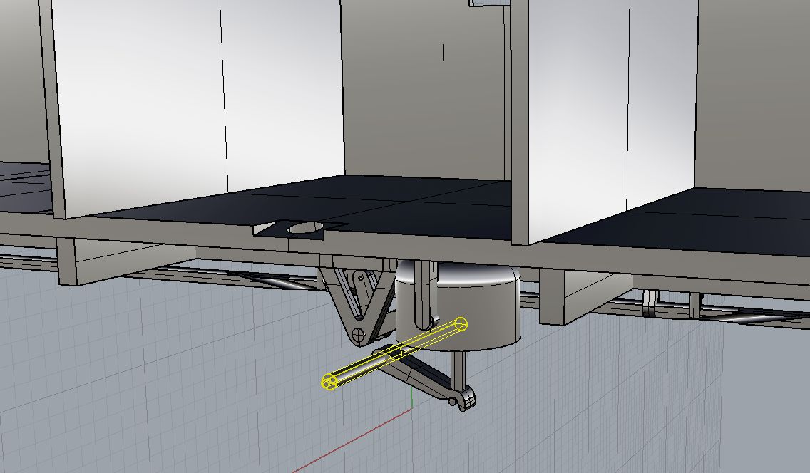
Because of the fine ribbing on the brake hoses, the 3D printer's automatic software has generated many support points, which have merged into one. Carefully cut between the brake hose and the support structure, using repeated cuts with a sharp knife (e.g. Olfa snap-off blade type or X-Acto knife with #11 blade), to separate the support structure, then carefully trim the remnants from the hose.
Note that on the underside of the roof, alternating ribs extend a short distance beyond the edge of the roof to interlock the two parts when it is time for final assembly.
Because of the fine ribbing on the brake hoses, the 3D printer's automatic software has generated many support points, which have merged into one. Carefully cut between the brake hose and the support structure, using repeated cuts with a sharp knife (e.g. Olfa snap-off blade type or X-Acto knife with #11 blade), to separate the support structure, then carefully trim the remnants from the hose.
 |
| Interlocking Parts |
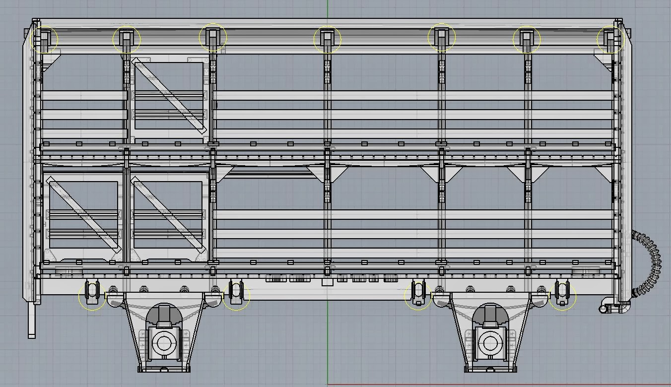
The support structure extends inside the upper and lower decks of the wagon to support the inside of the wagon sides. From the outside, cut through supports attached to the small circular brackets for the horizontal wires above the side planking on each deck, on the underside of the roof, and the underside of the middle floor. When you have cut as many of these supports as possible from the outside of the wagon, gently wiggling the supports structure (e.g. with needle nose pliers) from the open side, will break the remaining supports and allow pieces of the structure to be torn away. Be careful not to apply excessive force to avoid damaging the side planks and door areas.
Once the majority of the support structure has been removed, carefully go over both parts and cut away the small supports which typically extend from one part to another, for example, around the brake rigging and between the frame members of the underframe. An X-acto type hobby knife with a sharp pointed blade (Exacto #11 or similar) is quite useful for getting into the nooks and crannies.
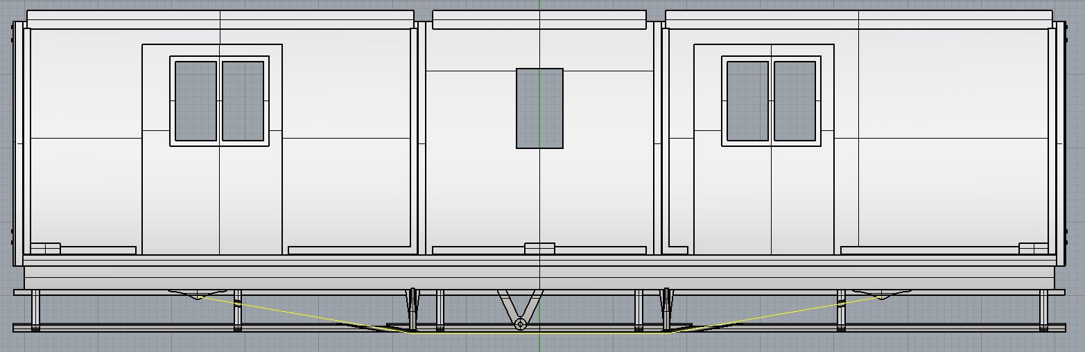
Go around the surfaces of each part where they will join together, and smooth off any remnants of the fine supports, on the roof, ends, middle and lower floors, etc. A sanding stick or small file can be useful for this, but be careful not to damage the projecting parts which are designed to interlock. Also remove any remnants from the very ends of the projecting parts. When you think you have finished, test fit the two halves together. Interlock the roof ribs first, then gently bring the underside of the wagon together to see how it fits. There are four frame members in the underframe which have retangular pins which fit into oval holes in their opposite number (a variation on the square peg in the round hole concept).
If the two halves don't close completely, dismantle again and check for and remove any tiny bumps from the support structure attachments.
Near each end of the wagon, there are small tabs designed for 1 mm x 3 mm long pan-head self tapping screws, to secure the two halves of the wagon together.
Near each end of the wagon, there are small tabs designed for 1 mm x 3 mm long pan-head self tapping screws, to secure the two halves of the wagon together.
In the long term, you have the option of gluing the body together, e.g. with superglue, or continuing to use the screw fixings. A half-way option is to just glue the roof area together, which would allow the join in the roof to be smoothed off, but would probably allow the underframe to be separated enough to change wheelsets, should that be necessary in the future.
As part of the clean-up stage, remove the four W-iron/axlebox assemblies which are attached to the rest of the wagon by four cylindrical supports (and probably some smaller supports). It is suggested to "nibble" through the supports with fine sidecutters rather than trying to cut through in one go. Once freed, the remnants of the supports should be cleaned up from both the W-iron/axlebox assemblies and the wagon sideframes.
Tapping Holes
Note: Tapping the coupler mounting holes is preferable to using self-tapping screws which may fracture the material. Although fairly robust, the material is more brittle than styrene or polyurethane.
Adding Wire Detailing

- A - 59.5 mm, above timber side rails, 4 pieces per side
- B - 13.5 mm, above timber side rails, upper deck only, 2 pieces per side
- C - 12 mm, upper doors, 2 pieces per side
- D - 24 mm, lower doors, 2 pieces per side
- E - 28.5 mm, upper door top guide, 1 piece per side
- F - 25 mm not including 90 degree bend on one end, brake pull rod, 1 piece per wagon
Also using 0.4 mm wire, form the handrails which are located vertically on the ends of the wagon, above the brake lever and shunter's step. The spacing between the holes is 6.5 mm.
W-Irons and Compensation Options
Either of the readily available etched brass W-irons can be used, i.e. the "closed" or "open" style. These are available from Railwest Models.
 |
| "Closed" (left) and "Open" W-irons. Photo courtesy of Railwest Models |
Remove the W-irons from the fret, fold them up and fit brass bearings in the usual way.
The underframe of the wagon includes eight small holes at each end for mounting the W-irons, using 1 mm x 3 mm pan-head self tapping screws, although each W-iron requires only two screws. (These are available from DCC Concepts part no. DCS-PH103.)
(Of course, you can glue the W-irons in position if you prefer, in which case the holes and grooves included in the underframe help to locate the W-irons in the correct position.)
Different sets of holes are used at each end, depending on the type of W-iron used and whether compensation is desired. Note that if using compensation, the rocking W-iron is positioned at the end of the wagon opposite the brake handle so that the rocking action does not interfere with the brake handle. The various options are:
Use the pair of holes at each end which are closest together (7 mm spacing) on the wagon centreline. Slide the W-irons (without wheels) sideways into position between the brake shoes, and fix them in position with screws.
Use the same holes as described above for no compensation, and fit the W-iron at the brake handle end without modification. However, at the end opposite the brake handle, remove the small brass tabs which project from the top surface of the W-Iron which then allows the W-Iron to rock sideways slightly using the fulcrum strip built into the chassis. After tightening the fixing screws on the rocking W-iron, back them off slightly to allow it to rock. It may be necessary to open out the etched holes in the W-iron slightly with a 1.1 mm drill bit or fine round file to obtain free movement.
At the brake handle end of the wagon, use the 7 mm spaced holes on the wagon centreline and fit the W-iron without modification.
At the end opposite the brake handle, remove the separate pivot bracket from the centre of the W-iron and fold up the ends to match the etched holes in the W-iron. It may be necessary to bend the ends slightly more than 90° to minimise slop in the rocking W-iron. The plan is to use the holes in the pivot bracket to secure the rocking W-iron to the wagon, using the pair of holes on the axle centreline spaced 7 mm apart.
As per the intended W-iron assembly procedure, pass a piece of brass wire (e.g. 1 mm diameter) through the pivot bracket and the corresponding holes in the side of the W-iron, and solder the wire on the outside only to the pivot bracket. Check that the W-iron can move freely with respect to the pivot bracket. Trim the excess wire from the outside of the W-iron, and file the wire and solder until it is almost flush with the sides of the W-irons to allow it to be slid sideways between the brake shoes, and fit two screws into the holes in the pivot bracket.
Use the fixing holes which are located on the axle centre line to fix both W-irons into position. One W-iron fits the holes which are 15 mm apart, while the other fits the holes which are 7 mm apart.
A styrene spacer approx. 0.75 mm thick will be necessary to achieve the correct height of the wagon above rail. On the end of the wagon opposite the brake handle, the spacer will need to be in two pieces to fit either side of the raised fulcrum strip.
A styrene spacer approx. 0.75 mm thick will be necessary to achieve the correct height of the wagon above rail. On the end of the wagon opposite the brake handle, the spacer will need to be in two pieces to fit either side of the raised fulcrum strip.
At the brake handle end of the wagon, use the fixing holes which are located on the axle centre line, 15 mm apart, to fix the W-iron into position. A styrene spacer approx. 0.75 mm thick will be necessary to achieve the correct height of the wagon above rail.
At the end opposite the brake handle, remove the separate pivot bracket from the centre of the W-iron and fold up the ends to match the etched holes in the W-iron. It may be necessary to bend the ends slightly more than 90° to minimise slop in the rocking W-iron. The plan is to use the holes in the pivot bracket to secure the rocking W-iron to the wagon, using the pair of holes on the wagon centre line spaced 10 mm apart. To allow clearance for the screw heads, file or grind a hollow in the side of the W-iron.
As per the intended W-iron assembly procedure, pass a piece of brass wire (e.g. 1 mm diameter) through the pivot bracket and the corresponding holes in the side of the W-iron, and solder the wire on the outside only to the pivot bracket. Check that the W-iron can move freely with respect to the pivot bracket. Cut the centre of the brass wire out, to allow access for the fixing screws. Cut the wire initially at a 45° angle to avoid forcing the sides of the W-iron apart, then cut the remaining section out leaving just enough to form the pivots for the rocking action. Also trim the excess wire from the outside of the W-iron, and file the wire and solder until it is almost flush with the sides of the W-irons to allow it to be slid sideways between the brake shoes.
To allow the pivot bracket to sit flush against the bottom of the underframe, grind away the raised fulcrum strip. Then, fix the W-iron in position with two screws.
Fit the wheels (26 mm axle length) and check that wagon sits at the correct height above the rails, i.e. the coupler mounting surfaces should be 11.5 mm above rail level, and adjust if necessary.
After checking that the wagon runs happily, fit the cosmetic W-iron/axlebox assemblies to the outside of the brass W-irons. It will probably be necessary to clean out the holes in the W-iron/axlebox assemblies with a 2 mm (or slightly larger) drill bit to fit over the brass bearings.
Weighting
With no additional weight, the completed wagon including wheels and couplers weighs around 38 grams. The "desirable" weight for a 4-wheel wagon is around 65-70 grams to ensure optimum operation including operation of Kadee couplers.
Addition of a Marbelup Models sheep load in Aluminide material adds approximately 24 grams, bringing the total weight up to around 62 grams.
If modelling an empty wagon, the weight can be increased by gluing lead shot or sheet lead between the various frame members of the underframe, where it would not be seen in normal operation.
Painting
Either enamel or acrylic hobby paints can be used to paint the finished model.
If desired, the interior of the wagon can be painted (airbrushed) prior to assembly. Experience to date suggests that this is probably not necessary as overspray from painting the outside tends to take away the "bare plastic" look on the inside surfaces.
Obviously, if a sheep load is to be included, it should be added after spray painting the wagon itself. Tamiya XF-78 Wooden Deck Tan is a reasonable colour for the sheep load.
Once the wagon is completely assembled, the join line on the roof can be filled and smoothed off. The join lines on the ends are virtually invisible as they are aligned with the angle iron end braces.
Back to Marbelup Models Home Page


.JPG)


.JPG)