|
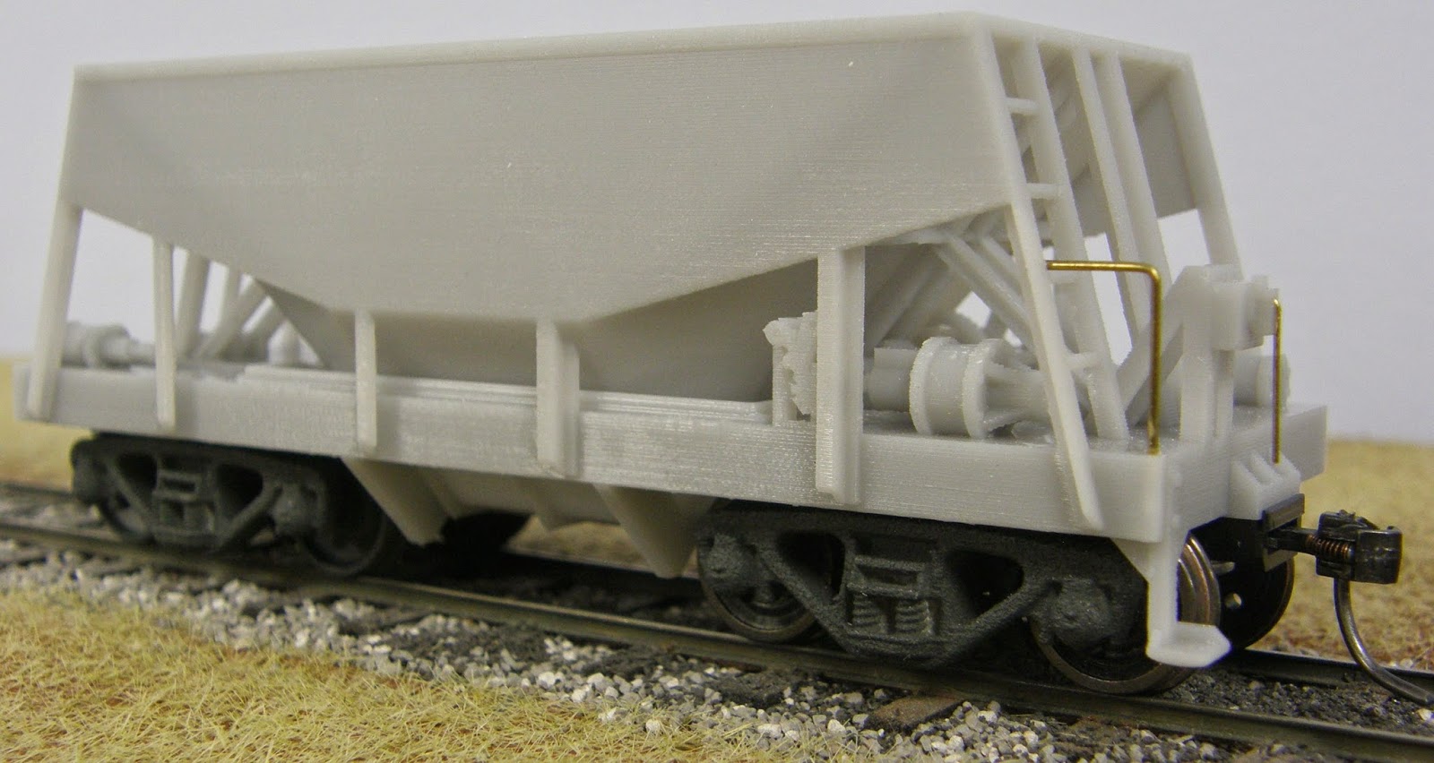
| TT3 (left) and S scale models with supports attached. |
Removing Support Structures
Carefully remove the support structure from the wagon. It is suggested to use a sharp knife to cut the supports away from visible areas. Take particular care around the end steps and the ends of the hopper doors where there are fine pull rods.
Note: Sometime, contrary to instructions, i.Materialise remove most of the support structures in the factory. Marbelup Models prefers that the supports structures are left attached in the factory as they help protect delicate parts of the models during handing and shipping.
Once the majority of the support structure has been removed, carefully go over the wagon and cut away the small supports which typically extend from one part to another, for example, around the door operating mechanism and other detail items. An Exacto type hobby knife with a sharp pointed blade (Exacto #11 or similar) is quite useful for getting into the nooks and crannies. For some parts, e.g. around the door actuating mechanism, where even a fine knife blade won't reach, a piece of wire (e.g. 0.8 mm spring steel wire) can be used to push against the support attachments and break them off. Another option is to sharpen the end of the spring steel wire to a chisel point, and secure the wire in a pin vice to form a tiny chisel.
Go over the model and smooth off any remnants of the fine supports, expecially in the visible areas. A sanding stick or small file can be useful for this. A hobby knife with a chisel type blade (Exacto #17 or similar) can also be useful for smoothing flat areas, such as the underside of the underframe,
Bogie and Coupler Mounting Holes
The coupler mounting holes for the HO version do go right through the floor due to the limited material thickness available. The holes should be tapped for HO versions only.
 |
| Grooved holes used for S and O scale versions. Tapping is not required for these holes. |
Bogies
Various options are available for bogies for the different scales. Some packing will most likely be required, depending on the bogies used, to achieve the correct wagon height above rail level.
Blackstone Models HOn3 Bettendorf Trucks #B370110 are potentially suitable, but have not been tried.
Caintode Flats produce a range of bogies for QR and Tasmanian models, and the shorter wheelbase Bettendorf style bogies may be suitable, but have not been tested.
TT3n½ Scale (10.5 mm gauge)
MicroTrains HOn3 Bettendorf bogies #00502020 were used on the Marbelup Models test model and fit well, although they represent an early 20th century design rather than the more usual mid-20th century Bettendorf style.Blackstone Models HOn3 Bettendorf Trucks #B370110 are potentially suitable, but have not been tried.
HOn3½ Scale (12 mm gauge)
Marbelup Models used Wuiske Models QRB008 Modern QR bogies on test models. They fit the NH and ENH models but don't suit the Tasmanian QA.HA version as they are fairly long wheelbase and the inner wheels foul the extra door stop parts.Caintode Flats produce a range of bogies for QR and Tasmanian models, and the shorter wheelbase Bettendorf style bogies may be suitable, but have not been tested.
Sn3½ Scale (16.5 mm gauge)
The bogie mounting points are designed to be 10 mm above rail level. Depending on the bogies used and the height of their bolsters, it may be necessary to add washers or similar so that the coupler mounting surface is 11.5 mm above rail level.Marbelup Models has 3D-printed bogies of the correct design for the WMC/WMD available for sale which are pretty close for this model. Please refer to the WMC/WMD Assembly Tips for more information on these bogies.
Similar bogies, although of slightly different shape, are available from Black Diamond Models in Queensland. The Black Diamond bogies are cast in white metal and are supplied fully assembled with wheels.
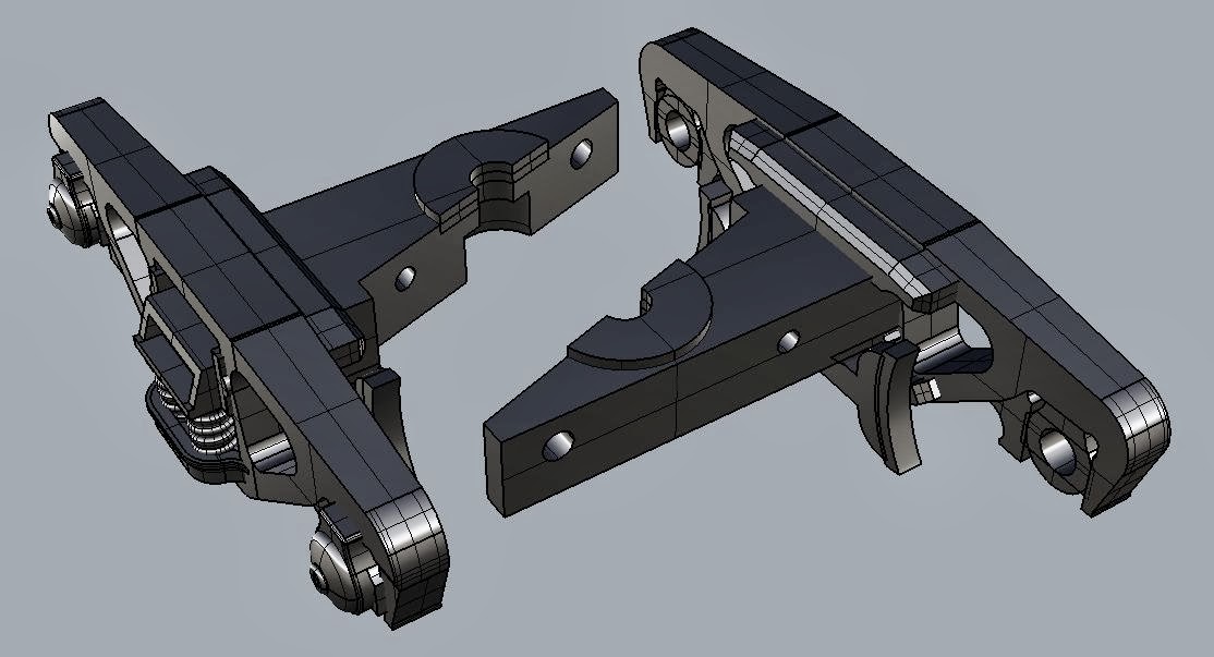 |
| Marbelup Models WMC/WMD Bogie |
On3½ Scale
Marbelup Models is not aware of any specific bogies which are available. Potentially, On3 or S scale standard gauge bogies could be suitable. Also, the Marbelup Models 3D-printed bogies for the WMC/WMD hopper wagon could potentially be printed in O scale, depending on the availability of suitable wheelsets.Couplers
As with bogies, there are various coupler options depending on the scale of the model. Because the models are 3D-printed "on demand", it is possible to customise the coupler mountings to suit specific requirement of individual modellers.
TT3n½ Scale
The TT3 version is currently designed to suit Kadee #711/#712 HO 3/4 size couplers set at a height of 7.8 mm to match the prototype coupler height. These couplers are the same as Kadee #713/#714 HOn3 couplers, other than having a longer trip pin to suit HO standard gauge models. For TTn3½ use, the trip pin on the #711/#712 will need to be shortened by about 2 mm to match the 7.8 mm coupler height.
Kadee #713/#714 couplers can also be used at the intended HOn3 height, which requires a shim of approx. 0.6-0.7 mm to bring the couplers down to the HOn3 height (7.14 mm).
Kadee #713/#714 couplers can also be used at the intended HOn3 height, which requires a shim of approx. 0.6-0.7 mm to bring the couplers down to the HOn3 height (7.14 mm).
HOn3½ Scale
The HO models are designed for Kadee HO "whisker" couplers at the HO standard gauge height (9.9 mm). Either the #158 (scale size) or #148 (normal size) couplers can be used, with #262 draft gear boxes.The draft gear boxes supplied with the couplers do not fit as they have a different mounting hole position. The #262 draft gear boxes are narrower and have been used because they provide more clearance for narrow gauge wheelsets. Also, the #262 draft gear boxes are easier to use as the lid snaps into position.
Note that the height from rail level to the coupler mounting surface should be 11.5 mm, the standard for Kadee HO couplers.
Sn3½ Scale
The S models are designed for Kadee HO "whisker" couplers at the HO standard gauge height (9.9 mm). Either the #158 (scale size) or #148 (normal size) couplers can be used, with #242 draft gear boxes which are the ones normally supplied with the whisker couplers. The reason for using the #242 draft gear boxes is that the mounting screws are closer to the end of the wagon (compared to #262 boxes) to avoid a clash with the outer axles.
Note that the height from rail level to the coupler mounting surface should be 11.5 mm, the standard for Kadee HO couplers. The 2-56 6.35 mm (1/4") long screws commonly used for couplers are slightly too long for the blind holes. Options are to shorten the screws by 0.5 to 1 mm, or to add a flat washer between the head of the screw and the coupler. Railwest Models sells suitable washers with a 2.2 mm hole diameter.
On3½ Scale (1:48 and 7 mm scale)
The 7 mm scale model is design for the Kadee #805 O Scale couplers or other Kadee couplers with the same mounting holes. If requested, the 1:48 scale model can also be configured for these couplers.Handrails and Brake Handle
Small starter holes have been provided to locate the L-shaped handrails on each end. One end also has a brake handle. These parts can be formed from brass wire and fixed in position with superglue. The hole for the vertical leg of the handrail is located near the corner of the underframe, and the hole for the horizontal leg is located just above the second rung of the ladder. Carefully drill out the starter holes - see below for drill sizes.
The suggested wire sizes and dimensions for the handrails for each scale are as follows:
TT3: 0.4 mm wire, 0.45 mm drill, horizontal: 4.5 mm, vertical: 8.5 mm
HO: 0.4 mm wire, 0.45 mm drill, horizontal: 5.5 mm, vertical: 9.5 mm
S: 0.6 mm wire, 0.65 mm drill, horizontal: 7.5 mm, vertical: 12.5 mm
O 1:48: 0.8 mm wire, 0.85 mm drill, horizontal: 10 mm, vertical: 16.5 mm
O 7 mm: 0.8 mm wire, 0.85 mm drill, horizontal: 11 mm, vertical: 18.5 mm
Note: The above measurements are a suggested starting point. Feel free to make adjustments as required.
 |
| Handrail and Brake Handle |
The brake handle is also an L-shape, with the shorter, horizontal portion fitting in a hole just above the centre of the handbrake mechanism. The suggested wire and drill sizes and dimensions for each scale are as follows:
TT3: 0.4 mm wire, 0.45 mm drill, horizontal: 1.5 mm, vertical: 6 mm
HO: 0.4 mm wire, 0.45 mm drill, horizontal: 2 mm, vertical: 7 mm
S: 0.4 mm wire, 0.45 mm drill, horizontal: 2 mm, vertical: 9 mm
O 1:48: 0.4 mm wire, 0.45 mm drill, horizontal: 2.5 mm, vertical: 12 mm
O 7 mm: 0.4 mm wire, 0.45 mm drill, horizontal: 2.5 mm, vertical: 13 mm
Painting
Either enamel or acrylic hobby paints can be used to paint the finished model. The test models have been painted with Revell Hobby Enamel No.83 "rust" which seemed a good match for the faded red/brown of the original NAR NH hoppers.
Back to Marbelup Models Home Page