Parts List
In addition to the 3D printed parts, the following parts must be obtained separately by the modeller:
- Brass wire for handrails, etc. (0.4 mm, 0.6 mm)
- Air hoses - e.g. Detail Associates #6206 (Vacuum brake hoses are included.)
- Handrail Posts (4) for uncoupling levers - e.g. Markits 1.5 mm(short - available from Railwest Models.
- Handrail Stanchions - see below.
- Bogie drive mechanisms - see below (Hollywood Foundry)
- Motor - Mashima 1833D Flat Can (double shaft, 2 mm diameter, includes fixing screws) (Hollywood Foundry)
- Drive shaft(s) - 1.5 mm diameter, approx 65 mm long (cut to exact length) (Brass rod is suitable.)
- Universal Joint set for 1.5 mm shafts (Hollywood Foundry)
- Flexible coupling(s) for motor end(s) of drive shafts - suggestion is to use model aircraft fuel tubing, approx. 1 mm ID, 4 mm OD.
- DCC decoder and speaker (both optional)
- Light Emitting Diodes (LEDs) for headlights 4 x 3 mm (sunny white)
- Optic fibre 2 mm diameter for headlights.
- LEDs (red and white) and optic fibre, if operating marker lights desired
- paint as desired
- decals - contact Westland Models.
- lead or other weighting material
- Kadee couplers #156 ("scale") or #146 (normal size)
- Kadee draft gear boxes #252
- Fixing screws for body, couplers and fuel tank e.g. Kadee #256 - 12 holes are included correct size (1.8 mm) ready for tapping 2-56.
- Fixing screws for speaker M1.4 x 6 (slightly longer is OK) - 4 holes are included correct size (1.1 mm) and screws should make their own thread, tapping shouldn't be required. Suitable screws are available from DCC Concepts - Part No. DCS-PHB156 or in assortment DCS-PHBSet. Although described as 1.5 mm, the DCC Concepts screws are actually M1.4 thread. Note: DCC Concepts now supplies pan-head and countersunk screws interchangeably, so you can't be sure of getting one or the other.
Bogie Drive Mechanisms
The bogie drive mechanisms can be ordered direct from Hollywood Foundry. The ordering specifications are as follows:
Drive bogie specifications: G16.5/B28.6+25/W14-110/15:1DUALBELT/NOBOL
Dummy bogie specifications: G16.5/B28.6+25/W14-110/NOBOL
To order the above bogie configurations, please use the
special order page on the Hollywood Foundry web site and copy and paste the above codes into the Product Description field.
The modeller has the choice of fitting two identical drive bogies or one drive bogie and a matching dummy bogie, depending on the required hauling capacity.
If a single drive bogie is fitted, this would normally be placed at the rear to keep the cab free for interior detailing if desired. However, the drive shaft is quite low above the footplate level, so there is minimal intrusion into the cab when two drive bogies are fitted.
The current (December 2014) pricing for the required Hollywood Foundry parts is:
Motor: Mashima
M1833D - $31.35
Universal Joint Set for 1.5 mm shafts (set contains parts for 4 joints. 1 joint is required per drive bogie, but it is recommended to purchase 1 set per loco to allow for some "spares".) - $4.19 per set
Drive shafts are available from Hollywood Foundry although the required 65 mm length is not a standard product. Check with Hollywood Foundry for availability. Alternatively, 1.5 mm brass or steel rod can be used.
Silicone Tubing - used for flexible coupling between motor and drive shaft(s). Supplied free by Hollywood Foundry if requested when ordering other parts. Tubing will fit both 2 mm motor shaft and 1.5 mm drive shaft.
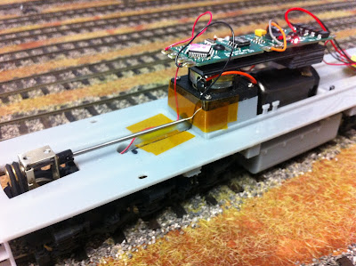 |
| The prototype 3D-printed chassis showing central motor, Tsunami AT-style DCC sound decoder, drive shaft, belt drive and speaker "duct" with tunnel for drive shaft. |
The chassis does not have provision for a flywheel. The main reason is that the motor is mounted low down, partly in the fuel tank, to get a "straight line" drive shaft alignment. Also, the speaker is very close to one end of the motor, which was necessary to avoid the narrow part of the body just behind the cab.
DCC and Sound
The chassis is specially designed to accept a 23 mm square high-bass speaker (Soundtraxx 810129 or equivalent) if a sound decoder is to be installed. The speaker faces downwards on a "sound duct" which has a "tunnel" through it for the front drive shaft.
Although the choice of specific sound decoder is very subjective, the Soundtraxx Alco 244 Tsunami decoder sounds similar to the English Electric diesel engine in the prototype, and is probably the closest available "off-the-shelf" decoder. The Tsunami "AT" style decoder model 828043 (pictured above) is suitable and slightly cheaper than the TSU-1000 style model 827104.
Note: The above links are for the SoundTraxx web site. SoundTraxx do not sell direct but their products are available from many retailers.
Couplers
The suggested couplers are both "long shank" style which avoids the problem of the "glad hand" on opposing couplers from fouling the cowcatcher. The choice between normal and "scale" size is up to the individual modeller.
Also, the suggested Kadee #252 draft gear boxes should be mounted upside down (as per the photo on the right on the Kadee web site). The round boss on the upper side needs to be trimmed away to allow the assembled coupler to slide into the headstock opening.
Other types of couplers can potentially be installed by modifying the headstock and/or coupler mounting pad.
Handrails
Unlike the chain handrails on the R class, the RA had solid handrails but with removable segments to allow the doors to be opened.
The 3D-printed chassis incorporates holes approx. 0.6 mm diameter to house the vertical handrail posts, typically cut from 0.6 mm brass wire.
One option for the handrails is to solder each section of handrails from 0.6 mm brass wire. Marbelup Models can supply a PDF template for the handrails on request. Note that the end walls of the cab have starter holes for the horizontal handrails. These should be carefully opened out with a 0.65 mm drill bit to a depth of approx. 1.5 mm.
Use of A-Line Handrail Stanchions
An alternative, which is potentially easier than soldering, is to use preformed steel handrail stanchions available from A-Line (Division of Proto-Power West, USA). These are available from various online hobby shops and/or eBay. (Marbelup Models has limited stocks of these stanchions available at $15 per pack of 35 stanchions.)
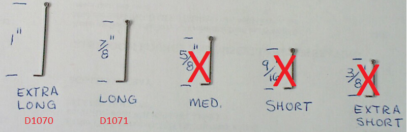 |
| A-Line Handrail Stanchions |
Although these stanchions are intended for HO locos, the two longest sizes are sufficiently long to be trimmed to the correct length for the RA. The A-line part numbers are D1071 (long) and D1071 (extra long). The stanchions should be trimmed at the bottom to a length of 18.5 mm, measured from the top of the "loop". For the handrails on the end platform, the stanchions should be trimmed to 17.5 mm. After trimming, file off any rough edges from the cut end. A total of 28 stanchions is required.
The holes in the 3D-printed chassis should be carefully drilled out to 0.75 mm to accommodate the stanchions (suggested drill size - test on some scrap plastic first). Carefully insert each stanchion vertically into the drilled hole, taking care to align the loop perpendicular to the sides of the loco. It is also suggested to orient all stanchions the same way, e.g. with the open side of the top loop inwards. Make sure the bottom of each stanchion is level with the underside of the running boards.
Once the stanchions are installed, 0.6 mm brass wire can be threaded through the line of stanchions to complete the handrail.
Where the handrails join onto the cab, there is a second, short handrail half-way up (See prototype photos.). If desired to replicate this feature, a short length of brass should be soldered onto the inside of each stanchion nearest the cab. Experience suggests the stanchions require light filing before soldering.
Once all the stanchions are in place and the long handrails threaded through, check that all the stanchions are vertical and make any necessary adjustments. Then, the brass handrail can be secured to each stanchion with superglue and, if desired, the stanchions glued into the holes in the running boards. Note that the short handrail in front of the cab (right side of loco only) should not be glued as it needs to be removed prior to separating the body and chassis, e.g. for maintenance.
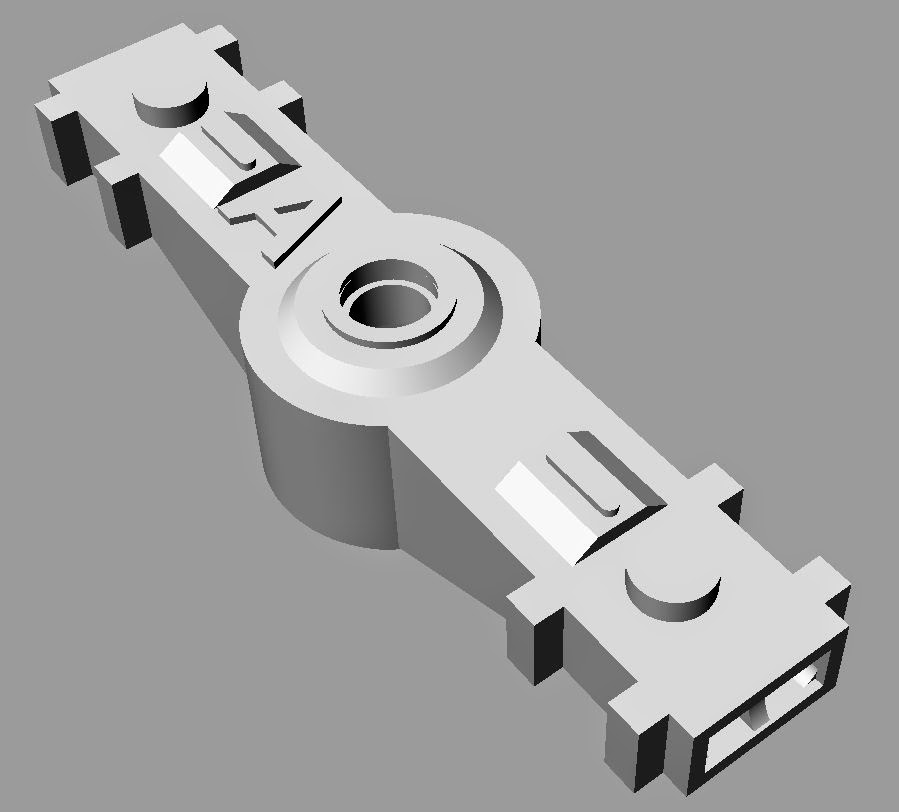
Chassis - Removal of Support Material
Carefully cut away the support materials from the delicate areas highlighted in the drawing below which are:
- Bolsters with bogie chain brackets approx. 6 mm in from edge of footplate (2 per side)
- Triangular footplate supports (4 per side)
- Sandboxes (2 per side)
Once these areas have been done, the remainder of the support material can be gently torn away by wiggling a section of it to break the fine attachment points.
The remnants of the support attachment points should be removed with a sharp hobby knife, filing or sanding on all visible areas, including the bogie attachment points.
Chassis Height
The finished height of the footplate should be 23 mm. Spacers with a nominal thickness of 1 mm are required between the Hollywood Foundry bogies and the underside of the footplate. The thickness of the spacers can be varied slightly, if required, to adjust the coupler height to match a Kadee coupler height gauge.
Headlights
The holes provided in the body shell for headlights are nominally 2.5 mm diameter, but typically slightly undersize due to the 3D printing process.
One method of lighting the headlights is to use a short length of optic fibre together with a 3 mm LED (Light Emitting Diode).
Note: Incandescent (filament) lamps are not recommended due to their high operating temperature which may damage the 3D print material.
At the rear of the loco, it is not practical to drill out the headlights to allow use of 2.5 mm diameter optic fibre, as the hole provided follows a curved path to allow for the high position of the headlights relative to the roof of the long hood. The suggested method is to carefully drill out the first 2-3 mm of the hole to 2.5 mm diameter, but use 2 mm diameter optic fibre which can bendto match the curved shape of the hole. The end of the optic fibre can be flared to approx. 2.5 mm diameter by holding it close to (but not touching) a hot soldering iron. With a little practice, the amount of flare can be judged to give a lens shape 2.5 mm in diameter. The same technique can be used for the front lights as well to avoid the need to purchase two difference sizes of optic fibre.
To attached the LED to the optic fibre, 3 mm black heatshink tubing is recommended. With the use of a hot air gun, the heatshrink tubing will shrink to form a snug fit over the optic fibre. However, the hot air may well be hot enough to melt the plastic optic fibre, so the trick is to shrink the tubing over the shank of a 2 mm drill bit, them slide the drill bit out and slide in the optic fibre.
Typical steps are:
- Cut heatshrink tubing to length, e.g. 8-10 mm.
- Hold 3 mm LED in a small vice by its legs, with the clear lens uppermost.
- Push the cut length of heatshrink tubing over the clear lens of the LED.
- Hold the shank of a 2 mm drill bit inside the heatshrink tubing while applying heat from a hot air gun.
- When it has cooled, withdraw the drill bit and insert the desired length of optic fibre. For the rear of the loco, you will probably have to feed the non-flared end of the optic fibre through the curved hole provided (from the outside) and attached the LED with attached heatshrink tubing on the inside.
For the dual headlights, it is simplest to wire the two LED in series as this simplifies the wiring and avoids the need for two separate resistors. A resistor of around 2K2 (2,200 ohms) is a suggested starting point for LEDs powered from DCC decoders.