Please Note - This is a "work in progress" with the idea of recording information while I am working on the construction and testing of the development models.
Update - June 2019. The design of the DA loco has been amended to suit the ViTrains mechanism, as used for the DB models, due to the unavailability of further Hollywood Foundry mechanisms. Refer to the Supplementary Instructions for details of the changes.
The correct size 15.7 mm wheels are available from Northyard in New Zealand.
Each loco requires 12 x 401N wheels, as illustrated in the following extract from the Northyard Catalogue:

Contact Northyard direct via email: northyard@xtra.co.nz for a quote for the wheels. The current (December 2014) catalogue price is NZ$1.80 per wheel.
It is up to the modeller's individual preference whether to fit two drive bogies or a single drive bogie plus a dummy bogie.
Drive bogie specifications: G16.5/B29.8+29.8/W15.7-110/22:
Dummy bogie specifications: G16.5/B29.8+29.8/W15.7-110/
Dummy bogie - $52.80 (same price as Bullant 3-axle Dummy)
Motor: Mashima M1833D - $31.35
Universal Joint Set for 1.5 mm shafts (set contains parts for 4 joints. 1 joint is required per drive bogie, but it is recommended to purchase 1 set per loco to allow for some "spares".) - $4.19 per set
Silicone Tubing - used for flexible coupling between motor and drive shaft(s). Supplied free by Hollywood Foundry if requested when ordering other parts. Tubing will fit both 2 mm motor shaft and 1.5 mm drive shaft.
Total price for two drive bogie configuration is $218.14 (plus approx $10 postage)
Total price for single drive bogie configuration is $171.94 (plus approx $10 postage)
Please not that the above prices set by Hollywood Foundry and are subject to change.
The underframe is designed for a nominal thickness of washers/packing of 1 mm between the top of the bogies and the mounting surface on the underframe.
The Hollywood Foundry bogies are supplied with two plastic shouldered washers, a formed phosphor bronze spring, a flat steel washer and an M1.4 machine screw.
For assembly to the 3D-printed underframe, it is recommended to discard the flat steel washer and upper plastic shouldered washer. This should result in the correct loco height from the rails and the phosphor bronze springs (at both ends) should minimise side-to-side rocking of the loco while allowing some movement to cope with uneven track.
Secure the bogie with the M1.4 screw provided, but don't tighten it fully so as to allow some for and aft rocking movement of the bogie as well.
To check the loco height, fit the underframe and body together, with couplers attached, and check the coupler height against a Kadee HO coupler height gauge. Be aware that the 3D-printed underframe is somewhat flexible on its own, and relies on the rigidity of the body to keep it straight and level. The top surface of the footplate should be 26 mm above rail level.
If the loco sits too low, a spacer should be cut from styrene and added above the phosphor bronze spring (or glued to the bogie pivot on the underframe). The spacer needs to be large enough, e.g. 8 mm square, so that the phosphor bronze spring is effective in minimise rocking.
If side-to-side rocking is still a problem, Marbelup Models can provide details to fabricate a mounting plate from brass sheet and wire which can be fitted to the top of the rear bogie, to provide a "3-point" suspension. Marbelup Models is also experimenting with a 3D-printed version of this mounting plate which is printed in high-detailed stainless steel at a cost of approx. $16.
The suggested couplers are Kadee #156 ("scale" head) or #146 (normal size head). These are both "long shank" style which avoids the problem of the "glad hand" on opposing couplers from fouling the cowcatcher. The choice between normal and "scale" size is up to the individual modeller. The suggested draft gear boxes are Kadee #262 which available separately in packs of 10 pairs. Kadee suggest assembling the coupler so that the main part of the draft gear box is on the bottom and the lid is on top. The draft gear boxes simply snap together.
If the coupler height is a little too high, a styrene spacer can be added between the couplers and the underframe. The bottom of the coupler opening in the end sill is only 0.5 mm thick, to allow it to be easily cut or filed if a deeper opening is required. If a spacer of more than 0.25 mm is required, it may also be necessary to trim the bottom flange from the Kadee draft gear box to clear the top of the cowcatcher.
The underframe is specially designed to accept a 23 mm square high-bass speaker (Soundtraxx 810129 or equivalent) if a sound decoder is to be installed. The speaker faces downwards on a "sound duct" which has a "tunnel" through it for the front drive shaft.
The underframe speaker mount include four holes, nominally 1.1 mm diameter, which are suitable for M1.4 fixing screws, 6-8 mm long. Ideally, the holes should be tapped with a M1.4 thread, but the screws can be inserted without tapping. (DCC Concepts sell suitable screws - part number DCS-NB14x6 or as part of an assortment DCS-Nbset.)


One handrail is inside the recessed step nearest the top on the left side of the loco, next to the radiator grilles. The spacing between the holes is 3.5 mm (centre-to-centre).
Starter holes are also provided on the end walls of the cab for the long handrails which run along the side of the loco - see below.
The 3D-printed chassis incorporates holes approx. 0.6 mm diameter to house the vertical handrail posts, typically cut from 0.6 mm brass wire.
Update - June 2019. The design of the DA loco has been amended to suit the ViTrains mechanism, as used for the DB models, due to the unavailability of further Hollywood Foundry mechanisms. Refer to the Supplementary Instructions for details of the changes.
Parts List (Preliminary - subject to change)
In addition to the 3D printed parts, the following parts must be obtained separately by the modeller:
- Brass wire for handrails, etc. (0.4 mm, 0.6 mm)
- Air hoses - e.g. Detail Associates #6206 (Vacuum brake hoses are included.)
- Handrail Knobs (4) for uncoupling levers - e.g. Markits 1.5 mm(short - available from Railwest Models.
- Handrail Stanchions (20 - optional) - A-Line D1071. Limited quantities available from Marbelup Models.
- Wheels - 12 x Northyard 401N - see below.
- Bogie drive mechanisms - see below (Hollywood Foundry)
- Motor - Mashima 1833D Flat Can (double shaft, 2 mm diameter, includes fixing screws) (Hollywood Foundry)
- Drive shaft(s) - 1.5 mm diameter, e.g. K&S #9862 (5 x 300 mm lengths per pack)
- Universal Joint set for 1.5 mm shafts (Hollywood Foundry)
- Flexible coupling(s) for motor end(s) of drive shafts (Hollywood Foundry).
- DCC decoder and speaker (both optional)
- Light Emitting Diodes (LEDs) for headlights 4 x 3 mm (sunny white) and optic fibre (2 mm)
- LEDs (red and white) and optic fibre, if operating marker lights desired
- paint as desired
- lead or other weighting material
- Kadee couplers #156 ("scale") or #146 (normal size)
- Kadee draft gear boxes #262
- Fixing screws for body, couplers and fuel tank e.g. Kadee #256 - 12 holes are included correct size (1.8 mm) ready for tapping 2-56.
- Fixing screws for speaker M1.4 x 6 (slightly longer is OK) - 4 holes are included correct size (1.1 mm) and screws should make their own thread, tapping shouldn't be required. Suitable screws are available from DCC Concepts - Part No. DCS-PHB156 or in assortment DCS-PHBSet. Although described as 1.5 mm, the DCC Concepts screws are actually M1.4 thread.
- Fixing screws (optional) for bogie sideframes - self tappers, 1 mm dia. x 3 mm long (8 required). Suitable screws are available from DCC Concepts - Part No. DCS-PH103
- Decals - Westland Models are developing decals for the original green WAGR livery and may also offer decals for later liveries.
Wheels
The correct size 15.7 mm wheels are available from Northyard in New Zealand.
Each loco requires 12 x 401N wheels, as illustrated in the following extract from the Northyard Catalogue:

Hollywood Foundry Drive Components
It is up to the modeller's individual preference whether to fit two drive bogies or a single drive bogie plus a dummy bogie.
Drive bogie specifications: G16.5/B29.8+29.8/W15.7-110/22:
Dummy bogie specifications: G16.5/B29.8+29.8/W15.7-110/
To order the above bogie configurations, please use the special order page on the Hollywood Foundry web site and copy and paste the above codes into the Product Description field.
The modeller should purchase the wheels from Northyard and send them to Hollywood Foundry in conjunction with each order.
The current (February 2016) pricing for the required Hollywood Foundry parts is:
Drive bogie - $91.30 (same price as Bullant In-Line 3-Axle)
Dummy bogie - $52.80 (same price as Bullant 3-axle Dummy)
Motor: Mashima M1833D - $31.35
Universal Joint Set for 1.5 mm shafts (set contains parts for 4 joints. 1 joint is required per drive bogie, but it is recommended to purchase 1 set per loco to allow for some "spares".) - $4.19 per set
Silicone Tubing - used for flexible coupling between motor and drive shaft(s). Supplied free by Hollywood Foundry if requested when ordering other parts. Tubing will fit both 2 mm motor shaft and 1.5 mm drive shaft.
Total price for two drive bogie configuration is $218.14 (plus approx $10 postage)
Total price for single drive bogie configuration is $171.94 (plus approx $10 postage)
Please not that the above prices set by Hollywood Foundry and are subject to change.
Bogie Pivot Assembly
| Note: Prior to assembling the Hollywood Foundry bogies to the underframe, place each bogie on a flat surface (glass is ideal) and check that the bogie doesn't rock from end to end. Some bogies have been found to have the centre axle set a fraction of a millimetre too low, which means the outer axles don't properly contact the rails and could cause derailments. If you are unlucky enough to experience this problem, contact Hollywood Foundry for repair or replacement under their Lifetime Warranty. |
The underframe is designed for a nominal thickness of washers/packing of 1 mm between the top of the bogies and the mounting surface on the underframe.
The Hollywood Foundry bogies are supplied with two plastic shouldered washers, a formed phosphor bronze spring, a flat steel washer and an M1.4 machine screw.
For assembly to the 3D-printed underframe, it is recommended to discard the flat steel washer and upper plastic shouldered washer. This should result in the correct loco height from the rails and the phosphor bronze springs (at both ends) should minimise side-to-side rocking of the loco while allowing some movement to cope with uneven track.
Secure the bogie with the M1.4 screw provided, but don't tighten it fully so as to allow some for and aft rocking movement of the bogie as well.
To check the loco height, fit the underframe and body together, with couplers attached, and check the coupler height against a Kadee HO coupler height gauge. Be aware that the 3D-printed underframe is somewhat flexible on its own, and relies on the rigidity of the body to keep it straight and level. The top surface of the footplate should be 26 mm above rail level.
If the loco sits too low, a spacer should be cut from styrene and added above the phosphor bronze spring (or glued to the bogie pivot on the underframe). The spacer needs to be large enough, e.g. 8 mm square, so that the phosphor bronze spring is effective in minimise rocking.
If side-to-side rocking is still a problem, Marbelup Models can provide details to fabricate a mounting plate from brass sheet and wire which can be fitted to the top of the rear bogie, to provide a "3-point" suspension. Marbelup Models is also experimenting with a 3D-printed version of this mounting plate which is printed in high-detailed stainless steel at a cost of approx. $16.
Drive Shaft Assembly
Brass rod 1.5 mm diameter is suitable for the drive shaft(s). The required length is approx 72-73 mm. Check the exact length required from your model. Allow some "end play" in the universal joint at the bogie end to accommodate movement of the bogie on curves or uneven track.
Hollywood Foundry have published an instruction sheet on the basic assembly. One end of each shaft requires a "flat" to be ground or filed to accommodate the male end of the plastic universal joint. Grind or file a flat on the shaft with a minimum length of about 2 mm. The depth of the flat should be 0.3 mm, so that the measurement over the remaining shaft is 1.2 mm. Don't force the joint onto the shaft if it is very tight, as it may split later.
Hollywood Foundry can supply silicone tubing (free on request with each order) for the motor end of each drive shaft. The tubing is sufficiently flexible to fit both the 1.5 mm drive shafts and 2 mm motor shaft.
The drive shaft for the front bogie of a loco with both bogies driven must pass through the "tunnel" in the speaker housing. One technique is to attach the drive shaft to the motor before installing the motor, then pass the drive shaft through the "tunnel" to engage with the universal joint on the bogie and, finally, fix the motor in position with the short M2 screws provided with the motor. The rear drive shaft can be attached to the motor last, as there is no "tunnel" to get in the way.
For a loco with one powered bogie, it is suggested to install the powered bogie at the rear to avoid the "tunnel" and leave the cab free for interior detailing, if desired.
Couplers
If the coupler height is a little too high, a styrene spacer can be added between the couplers and the underframe. The bottom of the coupler opening in the end sill is only 0.5 mm thick, to allow it to be easily cut or filed if a deeper opening is required. If a spacer of more than 0.25 mm is required, it may also be necessary to trim the bottom flange from the Kadee draft gear box to clear the top of the cowcatcher.
DCC and Sound
The underframe speaker mount include four holes, nominally 1.1 mm diameter, which are suitable for M1.4 fixing screws, 6-8 mm long. Ideally, the holes should be tapped with a M1.4 thread, but the screws can be inserted without tapping. (DCC Concepts sell suitable screws - part number DCS-NB14x6 or as part of an assortment DCS-Nbset.)
The recommended sound decoder is the Soundtraxx Tsunami EMD 645 Non-Turbo. The Tsunami "AT" style decoder model 828048 is suitable and slightly cheaper than the TSU-1000 style model 827109.
Note: The above links are for the SoundTraxx web site. SoundTraxx do not sell direct but their products are available from many retailers.
Note: The above links are for the SoundTraxx web site. SoundTraxx do not sell direct but their products are available from many retailers.
Body Preparation and Details
Take care when removing the support structure from the body, especially around the cab windows to avoid damaging the vertical dividers between the windows.
Once the body has been "cleaned up", it is also necessary to remove the two temporary braces which link the fixing posts near the centre of the body, as highlighted in yellow below. These have been included to protect the body during production and shipping, and must be cut away to provide clearance for the motor, etc. These can be cut with a fine-toothed razor saw or a cutting disk in a rotary tool, as low speed.

The eight fixing holes in the body shell should be tapped with a 2-56 thread. If necessary, clean out the holes prior to tapping using a 1.8 mm drill bit.
If using dual drive bogies, there are areas marked on the lower, end wall of the cab which need to be cut out to provide clearance for the front drive shaft and bogie mechanism. These are highlighted in yellow in the image below.

Handrails
Starter holes are provided on the body for three handrails which can be formed from brass wire (e.g. 0.3 or 0.4 mm). The started holes should be drilled out slightly larger, e.g 0.05 mm larger than the wire size.
One handrail is inside the recessed step nearest the top on the left side of the loco, next to the radiator grilles. The spacing between the holes is 3.5 mm (centre-to-centre).
 |
| Photo by G Stallard |
The other two handrails are on the roof, adjacent to the recessed steps. The spacing between the holes is 8 mm. Photos indicated that the bends in the top handrails should have a radius of approx. 1.5 mm. Radiussed corners can be formed by bending the wire around the shank of a drill bit, or using special pliers with round jaws.
 |
| Photo by G Stallard |
Long Handrails on Underframe
One option for the handrails is to solder each section of handrails from 0.6 mm brass wire. Marbelup Models can supply a PDF template for the handrails on request or download it from D/DA Handrail Template. If printing the template yourself, make sure you print at 100% scaling to get the correct size.
Note that the end walls of the cab have starter holes for the horizontal handrails. Assuming 0.6 mm wire is used for the long handrails (and shorter ones at the front of the loco), it is suggested to drill the holes in the cab end walls slightly larger e.g. 0.7 mm, so the handrails are an easy fit. Ideally, the handrails should be trimmed so that just enough extends into the holes (e.g. 0.5 mm) so they they appear to be attached when the loco is fully assembled. If the handrails extend too far into the holes in the can, it will be more difficult to disassembly the loco.
Note that the end walls of the cab have starter holes for the horizontal handrails. Assuming 0.6 mm wire is used for the long handrails (and shorter ones at the front of the loco), it is suggested to drill the holes in the cab end walls slightly larger e.g. 0.7 mm, so the handrails are an easy fit. Ideally, the handrails should be trimmed so that just enough extends into the holes (e.g. 0.5 mm) so they they appear to be attached when the loco is fully assembled. If the handrails extend too far into the holes in the can, it will be more difficult to disassembly the loco.
Use of A-Line Handrail Stanchions
An alternative, which is potentially easier than soldering, is to use preformed steel handrail stanchions available from A-Line (Division of Proto-Power West, USA). These are available from various online hobby shops and/or eBay. (Marbelup Models has limited stocks of these stanchions available at $15 per pack of 35 stanchions.)
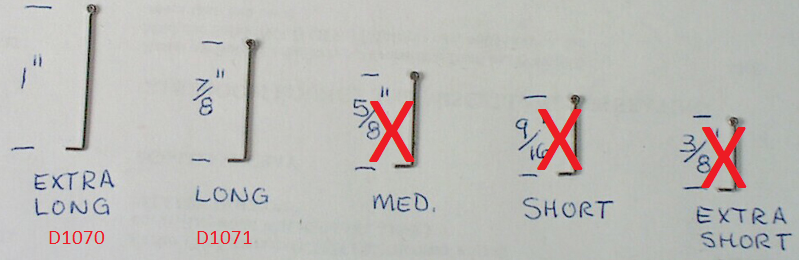 |
| A-Line Handrail Stanchions |
Although these stanchions are intended for HO locos, the two longest sizes are sufficiently long to be trimmed to the correct length for the D and A. The A-line part numbers are D1071 (long) and D1071 (extra long). The stanchions should be trimmed at the bottom to a length of 18.5 mm, measured from the top of the "loop". For the handrails on the end platform, the stanchions should be trimmed to 17.5 mm. After trimming, file off any rough edges from the cut end.
The holes in the 3D-printed chassis should be carefully drilled out to accommodate the stanchions (suggested drill size: 0.75 mm - test on some scrap plastic first). Carefully insert each stanchion vertically into the drilled hole, taking care to align the loop perpendicular to the sides of the loco. It is also suggested to orient all stanchions the same way, e.g. with the open side of the top loop inwards. Make sure the bottom of each stanchion is level with the underside of the running boards.
Once the stanchions are installed, 0.6 mm brass wire can be threaded through the line of stanchions to complete the handrail. Some custom bending will be required at the ends of the loco and where the height of the handrail varies. The PDF template may be useful for this.
Once all the stanchions are in place and the long handrails threaded through, check that all the stanchions are vertical and make any necessary adjustments. Then, the brass handrail can be secured to each stanchion with superglue and, if desired, the stanchions glued into the holes in the running boards. Note that the short handrails in front of the cab should not be glued as they may need to be removed prior to separating the body and chassis, e.g. for maintenance.
Horns
Four horns are included as part of the 3D-printed underframe. Carefully remove them from the underframe, leaving the spigots attached to the horns intact as much as possible. Only two are required, with two spares.
(Alternate horns can be source from detail parts suppliers e.g. in brass, if greater robustness is desired.)
Starter holes are provided for the horns on the rear wall of the cab (right side) and on the front wall of the cab (both sides). Early photos show the front horn on the right side of the loco (as pictured below) and later photos show the front horn on the left side of the loco. Consult photos appropriate to the era being modelled to determine correct horn placement.
Drill out the starter holes to suit the diameter of the spigot on the back end of the horns. Carefully trim the unwanted spigot projecting sideways from the horn.
 |
| Photo courtesy of Rail Heritage WA. |
Headlights
The holes provided in the body shell for headlights are nominally 1.8 mm diameter, but typically slightly undersize due to the 3D printing process. The headlights should be 2 mm in diameter, so drill the holes out to 2 mm taking care not damage the thin surround around the hole.
(The holes are deliberately undersize because the thin surround would not print otherwise, as the minimum detail thickness is 0.5 mm. and the outside diameter of the surround is 2.8 mm.)
(The holes are deliberately undersize because the thin surround would not print otherwise, as the minimum detail thickness is 0.5 mm. and the outside diameter of the surround is 2.8 mm.)
One method of lighting the headlights is to use a short length of optic fibre together with a 3 mm LED (Light Emitting Diode).
The D and DA locos had "sealed beam" headlights for which "sunny white" LEDs are a suitable approximation. (Many older locos had larger diameter headlights with replaceable bulbs which tended to have a more yellow appearance, similar to "golden yellow" LEDs.)
The D and DA locos had "sealed beam" headlights for which "sunny white" LEDs are a suitable approximation. (Many older locos had larger diameter headlights with replaceable bulbs which tended to have a more yellow appearance, similar to "golden yellow" LEDs.)
Note: Incandescent (filament) lamps are not recommended due to their high operating temperature which may damage the 3D print material.
To attach the LED to the optic fibre, 3 mm black heatshink tubing is recommended. With the use of a hot air gun, the heatshrink tubing will shrink to form a snug fit over the optic fibre. However, the hot air may well be hot enough to melt the plastic optic fibre, so the trick is to shrink the tubing over the shank of a 2 mm drill bit, them slide the drill bit out and slide in the optic fibre.
Typical steps are:
- Cut heatshrink tubing to length, e.g. 8-10 mm.
- Hold 3 mm LED in a small vice by its legs, with the clear lens uppermost.
- Push the cut length of heatshrink tubing over the clear lens of the LED.
- Hold the shank of a 2 mm drill bit inside the heatshrink tubing while applying heat from a hot air gun.
- When it has cooled, withdraw the drill bit and insert the desired length of optic fibre. For the rear of the loco, you will probably have to feed the non-flared end of the optic fibre through the curved hole provided (from the outside) and attached the LED with attached heatshrink tubing on the inside.
CAUTION: Do not used the hot air gun or other heat source to shrink the heatshrink tubing in close proximity to the loco body or other 3D printed parts as they may distort due to the heat.
For the dual headlights, it is simplest to wire the two LED in series as this reduces the wiring and avoids the need for two separate resistors. A resistor of around 2K2 (2,200 ohms) is a suggested starting point for LEDs powered from DCC decoders.
A "conduit" has been provided in the roof of the cab to allow the headlight wires to be fed through into the short hood.
Marker lights can also be drilled out and illuminated if desired.
A "conduit" has been provided in the roof of the cab to allow the headlight wires to be fed through into the short hood.
Marker lights can also be drilled out and illuminated if desired.
No comments:
New comments are not allowed.