Monday 19 June 2017

DB Loco Mechanism Options

As an aid to deciding which mechanism to use for Marbelup Models DB Locomotive, the following summarises the main features of the Hollywood Foundry (HF) and ViTrains (VT) mechanisms.

Comparison of ViTrains bogie (left) and Hollywood Foundry bogie (right)

Bogie Wheelbase


Prototype: 3810 mm = 59.5 mm in S scale
HF Bogie: 59.5 mm
VT Bogie: 58 mm

Wheel Diameter


Prototype: 1016 mm = 15.875 mm in S scale
HF Bogie: 15.7 mm
VT Bogie: 14.8 mm Note: Upper part of wheels is largely hidden by bogie sideframes

Flange Depth


HF Bogie: 0.65 mm (RP25)
VT Bogie: 1 mm - operates on Code 70 or larger rail

Cost (for drive bogies and motor):


HF Single Bogie Drive: Approx. $200
HF Double Bogie Drive: Approx. $250
VT Drive: $140

HF Mechanism Features


  • Choice of 6-wheel (single bogie) or 12-wheel (dual bogie) drive
  • For single bogie drive, cab area is clear to allow for interior detailing
  • Worm gear on each driven axle, with dual belt drive from bogie input shaft

VT Mechanism Features


  • 8-wheel drive (centre axles are idlers and lightly sprung)
  • Twin flywheels included
  • Smoother operation
  • Quieter operation
  • Cab area is clear to allow for interior detailing
  • Worm gear on each bogie with spur gearing to powered axles
Back to Marbelup Models Home Page

Sunday 4 June 2017

DB Loco Hollywood Foundry Underframe Assembly Tips

Hollywood Foundry Drive Components


It is up to the modeller's individual preference whether to fit two drive bogies or a single drive bogie plus a dummy bogie.

Drive bogie specifications: G16.5/B29.8+29.8/W15.7-110/22:1DUALBELT/NOBOL
Dummy bogie specifications: G16.5/B29.8+29.8/W15.7-110/NOBOL

To order the above bogie configurations, please use the special order page on the Hollywood Foundry web site and copy and paste the above codes into the Product Description field.  

The modeller should purchase the wheels, 15.7 mm diameter, from Northyard in New Zealand and send them to Hollywood Foundry in conjunction with each order.  Marbelup Models has a limited quantity of Northyard wheels available for purchase for $35 per set of 12 wheels.


Contact Northyard direct via email: northyard@xtra.co.nz for a quote for the wheels.  The current (September 2016) catalogue price is NZ$1.95 per wheel (not including postage).

Each loco requires 12 x 401N wheels, as illustrated in the following extract from the Northyard Catalogue:


The current (February 2016) pricing for the required Hollywood Foundry parts is:

Drive bogie - $91.30 (same price as Bullant In-Line 3-Axle)

Dummy bogie - $52.80 (same price as Bullant 3-axle Dummy)

Motor: Mashima M1833D - $31.35

Universal Joint Set for 1.5 mm shafts (set contains parts for 4 joints.  1 joint is required per drive bogie, but it is recommended to purchase 1 set per loco to allow for some "spares".) - $4.19 per set

Silicone Tubing - used for flexible coupling between motor and drive shaft(s).  Supplied free by Hollywood Foundry if requested when ordering other parts.  Tubing will fit both 2 mm motor shaft and 1.5 mm drive shaft.

Total price for two drive bogie configuration is $218.14 (plus approx $10 postage)
Total price for single drive bogie configuration is $171.94 (plus approx $10 postage)

Please not that the above prices set by Hollywood Foundry and are subject to change.

As of late 2016, Mashima Motors are no longer in production.  Marbelup Models has designed the chassis to accommodate other motors including Canon, which are available from some hobby shops in the same size as the Mashima M1833D.  Marbelup Models also has limited stock of another alternate motor which will fit in the space available.


Bogie Pivot Assembly (Hollywood Foundry)


Note:  Prior to assembling the Hollywood Foundry bogies to the underframe, place each bogie on a flat surface (glass is ideal) and check that the bogie doesn't rock from end to end.  Some bogies have been found to have the centre axle set a fraction of a millimetre too low, which means the outer axles don't properly contact the rails and could cause derailments.  If you are unlucky enough to experience this problem, contact Hollywood Foundry for repair or replacement under their Lifetime Warranty.

The underframe is designed for a nominal thickness of washers/packing of 1 mm between the top of the bogies and the mounting surface on the underframe.

The Hollywood Foundry bogies are supplied with two plastic shouldered washers, a formed phosphor bronze spring, a flat steel washer and an M1.4 machine screw. 

For assembly to the 3D-printed underframe, it is recommended to discard the flat steel washer and upper plastic shouldered washer.  This should result in the correct loco height from the rails and the phosphor bronze springs (at both ends) should minimise side-to-side rocking of the loco while allowing some movement to cope with uneven track.

Secure the bogie with the M1.4 screw provided, but don't tighten it fully so as to allow some for and aft rocking movement of the bogie as well.

To check the loco height, fit the underframe and body together, with couplers attached, and check the coupler height against a Kadee HO coupler height gauge.  Be aware that the 3D-printed underframe is somewhat flexible on its own, and relies on the rigidity of the body to keep it straight and level.  The top surface of the footplate should be 26 mm above rail level.

If the loco sits too low, a spacer should be cut from styrene and added above the phosphor bronze spring (or glued to the bogie pivot on the underframe).  The spacer needs to be large enough, e.g. 8 mm square, so that the phosphor bronze spring is effective in minimise rocking.

If side-to-side rocking is still a problem, Marbelup Models can provide details to fabricate a mounting plate from brass sheet and wire which can be fitted to the top of the rear bogie, to provide a "3-point" suspension.  Marbelup Models has also produced a 3D-printed version of this mounting plate which is printed in high-detailed stainless steel at a cost of approx. $16.

Drive Shaft Assembly (Hollywood Foundry)


Brass rod 1.5 mm diameter is suitable for the drive shaft(s).  The required length is approx xx mm.  Check the exact length required from your model.  Allow some "end play" in the universal joint at the bogie end to accommodate movement of the bogie on curves or uneven track.

Hollywood Foundry have published an instruction sheet on the basic assembly. One end of each shaft requires a "flat" to be ground or filed to accommodate the male end of the plastic universal joint.  Grind or file a flat on the shaft with a minimum length of about 2 mm.  The depth of the flat should be 0.3 mm, so that the measurement over the remaining shaft is 1.2 mm.  Don't force the joint onto the shaft if it is very tight, as it may split later.

Hollywood Foundry can supply silicone tubing (free on request with each order) for the motor end of each drive shaft.  The tubing is sufficiently flexible to fit both the 1.5 mm drive shafts and 2 mm motor shaft.

The drive shaft for the front bogie of a loco with both bogies driven must pass through the "tunnel" in the speaker housing.  One technique is to attach the drive shaft to the motor before installing the motor, then pass the drive shaft through the "tunnel" to engage with the universal joint on the bogie and, finally, fix the motor in position with the short M2 screws provided with the motor.  The rear drive shaft can be attached to the motor last, as there is no "tunnel" to get in the way.

For a loco with one powered bogie, it is suggested to install the powered bogie at the rear to avoid the "tunnel" and leave the cab free for interior detailing, if desired.

DB Loco ViTrains Underframe Assembly Tips


ViTrains Drive Components


Remove the plastic body from the ViTrains Class 47 locomotive by gently easing the body sides out to disengage the lateral grooves on the chassis, as per the instruction sheet supplied with the loco.

Unsolder the wires connecting to the bogies and motor (3 green, 3 black) from the Printed Circuit Board (PCB) on the ViTrains chassis.

Unscrew the 4 black screws and remove the PCB.  

Remove the motor and its rubber mounting block. 

Unclip the bogies by gently pressing on the raised clip which engages in the curved slot in the chassis.  Take care with this step as the clip can break if bent excessively.  

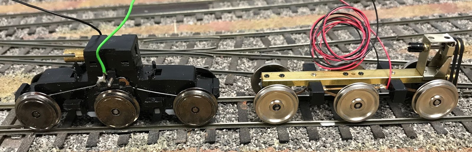
Set aside the two bogies and motor with their wires attached.  All other parts of the loco can be discarded.


Bogie Sideframe Assembly


Unclip the keeper plate/sideframe assembly from the underside of each bogie.  There are clips at each end and on each side between the wheels.

Using a fine-bladed razor saw, or similar, cut off the dummy Class 47 sideframes flush with the insides of the sideframes, as per photo below.  Also cut the smaller attachment points at the ends of the keeper plate.  Discard the dummy Class 47 sideframes.

Cut lines to remove dummy Class 47 sideframes.

Remove the support structure and clean up the 3D-printed bogie sideframes.

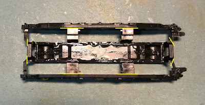
Remove the central "sprue" from the bogie sideframes as per the diagram below.  The cut lines are highlighted below  in yellow.  Also cut away the raised section, highlighted in red, where the sprue is attached to the end "traction motor".  Part of the "sprue" is (optionally) reattached later, to represent the traction motors.

Cut lines for 3D-Printed Sideframes

Optionally, the parts of the previously-removed "sprue" can be fitted to the underside of the keeper plate to provide a representative profile of the traction motors, when the finished loco is viewed side on at track level.  

At this stage, the central joining piece (highlighed in red, below) can be left intact.  Position the two "traction motors" aligned with the matching notches in the ViTrains bogie.  Orientation is not important.  Carefully, drill two 0.8 mm holes through the holes in the "traction motors" for 1 mm dia. x 3 mm long fixing screws.  After drilling the holes, remove the central joining piece and attach the individual "traction motors".  Don't use screws longer than 3 mm as clearance is needed for the gears.

Adding dummy "Traction Motors" to Keeper Plate

Reassemble the keeper plate to the ViTrains bogie. The orientation of the keeper plate is important at this stage.  Each of the "traction motors" should be inboard of its respective axle.  The orientation will be correct if the keeper plate and bogie are orientated as per the photos above and below.

If the wheels fell out previously, ensure that the power collection wires are correctly located in the grooves on the inside faces of the wheels.

ViTrains Bogie after Reassembly

Attach the 3D-printed sideframe to the ViTrains bogie, from below.  First, insert the end of the bogie (closest to the brass shaft coupling) into the dummy "traction motor" recess on the end of the 3D-printed sideframe.  Gently spread the 3D-printed sideframe apart to allow the projections on the ViTrains bogie to engage in the rectangular holes on the inside of the 3D-printed sideframe.

Fitting 3D-Printed Sideframes to ViTrains Bogie
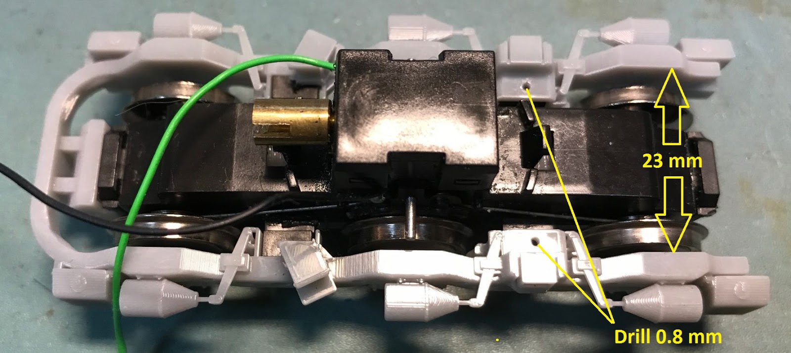
Check that the sideframes are fully engaged with the ViTrains bogie by measuring the distance between the insides of the sideframes.  It should measure 23 mm.  If the measurement is greater, check that the rectangular holes on the inside of the 3D-printed sideframes are free of supports, and remove any burrs from the cut ends of the ViTrains bogie.

Once satisfied with the fit, gently squeeze the sideframes together while drilling two 0.8 mm diameter holes into the ViTrains bogie frame, using the small holes provided in the 3D-printed sideframes as a guide.  Use 1 mm dia. x 3 mm long screws to secure the 3D-printed sideframes in position.

Clip the assembled bogies into the "oval" holes in the underframe.  Again, take care with this step to avoid breaking the clips on the bogies.  The green wires should be on the left side of the loco.

Motor and Drive Shaft Installation


Remove the drive shafts and motor clamp from the separate parts "sprue", and clean up the individual parts.

Position the motor in the recess in the underframe, with the wires towards the rear of the loco, and the motor clamp on top.  Secure motor clamp in place with four 2-56 screws.  After checking that the motor clamp is level, measure the excess length for each screw and trim screws to length, e.g. with a cutting disc in a Dremel or similar motor tool.  The remaining screw length should be about 21 mm.

Before refitting the motor clamp, insert the 3D-printed drive shafts into the mating fittings on the bogies and motor flywheels.

Refit the motor clamp and secure with screws trimmed previously.  

Rotate the flywheels by hand to check the motor rotates smoothly.

Height Above Rail Level

The top of the footplate should be 26 mm above the top of the rails.  If necessary, minor adjustments can be made by adding packing (e.g. thin sheet styrene) between the bogies and underframe.  Note that the underframe on its own is slightly flexible, so checking of the height should be done with the loco body attached.

At the front end of the loco, packing can be inserted on the underside of the U-shaped bracket which rests on the top of the bogie assembly.

At the rear end of the loco, packing, can be inserted in the crescent-shaped cutouts which rest on the short metal rods protruding sideways from the bogie assembly.  Alternatively, the short metal rods can be bent slightly upwards or downwards, taking care that they are the same on both sides so that the loco sits level.

Note that the underframe is designed so that the front bogie can rock slightly from side to side to accommodate minor track irregularities, such as when entering a superelevated curve.  

Wiring

For DC operation, connect the 3 green wires to each other and connect the 3 black wires to each other.  Verify that the loco moves in the correct direction.  The loco should move forward when the left rail is negative and and the right rail is positive - or check the direction against other DC locos.  They should all move in the same direction on the same powered section of track.

For DCC operation, connect the bogie pickup and motor wires to the DCC decoder in accordance with the decoder wiring instructions.  The green pickup wires are equivalent to the red wires (left side) for standard DCC wiring.