Removing Support Structures
Carefully remove the support structure from the wagon. It is suggested to use a sharp knife to cut the supports away from visible areas. Take particular care around the brake hoses and end steps.
Once the majority of the support structure has been removed, carefully go over the wagon and cut away the small supports which typically extend from one part to another, for example, around the brake cylinders and other detail items. An Exacto type hobby knife with a sharp pointed blade (Exacto #11 or similar) is quite useful for getting into the nooks and crannies. For some parts around the brake cylinders where even a fine knife blade won't reach, a piece of wire (e.g. 0.8 mm spring steel wire) can be used to push against the support attachments and break them off.
Once the majority of the support structure has been removed, carefully go over the wagon and cut away the small supports which typically extend from one part to another, for example, around the brake cylinders and other detail items. An Exacto type hobby knife with a sharp pointed blade (Exacto #11 or similar) is quite useful for getting into the nooks and crannies. For some parts around the brake cylinders where even a fine knife blade won't reach, a piece of wire (e.g. 0.8 mm spring steel wire) can be used to push against the support attachments and break them off.
Go over the model and smooth off any remnants of the fine supports, expecially in the visible areas. A sanding stick or small file can be useful for this.
Bogie and Coupler Mounting Holes
Bogies
The bogie mounting points are designed to be 10 mm above rail level. Depending on the bogies used and the height of their bolsters, it may be necessary to add washers or similar so that the coupler mounting surface is 11.5 mm above rail level.
Marbelup Models has 3D-printed bogies of the correct design for the WMC/WMD available for sale. Similar bogies, although of slightly different shape, are available from Black Diamond Models in Queensland. The Black Diamond bogies are cast in white metal and are supplied fully assembled with wheels.
The Marbelup Models WMC/WMD bogies are printed in two identical halves. A set contains four pieces to make one pair of bogies. As with other 3D printed parts, the first step is to removed the supports structure and clean up the small supports in the holes in the bogie sideframes, around the springs, etc. Take care around the brake shoes to avoid breaking them.
The bolster section of each bogie half contains two holes intended for M1.4 screws (which are supplied with the bogies). The larger hole nearest the narrow end of the bolster is a "clearance" hole and should be cleaned out with a 1.4 mm drill. The smaller hole, nearest the bogie sideframe, should cleaned out with a 1.1 mm drill and tapped with an M1.4 tap. (Drills and taps are available from North Yard in New Zealand. The M1.4 tap is part No. 3014. Refer to Page 5 of the North Yard Catalogue.)
An alternative to M1.4 screws is to use 1.5 mm x 6 mm self tapping screws, which are available from DCC Concepts - Part No. DCS-PH156. If using self tapping screws, the smaller holes should be drilled out to 1.1 or 1.2 mm. If the screws seem tight with 1.1 mm holes, try 1.2 mm, especially with bogies printed in Standard Resin (clear yellow rather than grey), which is somewhat less flexible. The clearance holes should be drilled to 1.5 mm.
The bogie sideframes contain holes for fitting brass pinpoint bearings (available from Railwest Models). These holes should be cleaned out with a 2 mm drill bit, after which the bearings should press fit into place. The bogie is designed for 12 mm wheels with 26 mm axles.
When assembling the two halves, it may be necessary to trim the narrow end of the bolster by approx. 0.25 mm to get good alignment of the fixing holes and centre pivot hole. (Later production will be made slightly shorter.) After assembly, clean out the centre pivot hole with a 2.2 mm drill bit to suit 2-56 mounting screws. (2.2 mm provides adequate clearance without excessive slop.)
 |
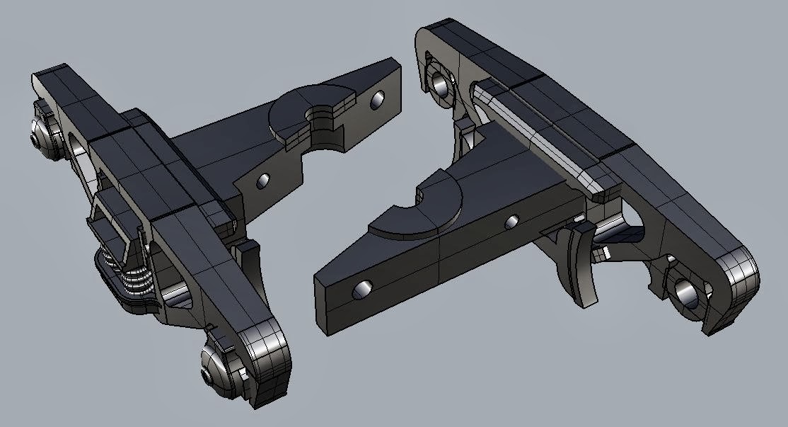
| Marbelup Models WMC/WMD Bogie |
Assembly of 3D-Printed Bogies

The Marbelup Models WMC/WMD bogies are printed in two identical halves. A set contains four pieces to make one pair of bogies. As with other 3D printed parts, the first step is to removed the supports structure and clean up the small supports in the holes in the bogie sideframes, around the springs, etc. Take care around the brake shoes to avoid breaking them.
The bolster section of each bogie half contains two holes intended for M1.4 screws (which are supplied with the bogies). The larger hole nearest the narrow end of the bolster is a "clearance" hole and should be cleaned out with a 1.4 mm drill. The smaller hole, nearest the bogie sideframe, should cleaned out with a 1.1 mm drill and tapped with an M1.4 tap. (Drills and taps are available from North Yard in New Zealand. The M1.4 tap is part No. 3014. Refer to Page 5 of the North Yard Catalogue.)
An alternative to M1.4 screws is to use 1.5 mm x 6 mm self tapping screws, which are available from DCC Concepts - Part No. DCS-PH156. If using self tapping screws, the smaller holes should be drilled out to 1.1 or 1.2 mm. If the screws seem tight with 1.1 mm holes, try 1.2 mm, especially with bogies printed in Standard Resin (clear yellow rather than grey), which is somewhat less flexible. The clearance holes should be drilled to 1.5 mm.
When assembling the two halves, it may be necessary to trim the narrow end of the bolster by approx. 0.25 mm to get good alignment of the fixing holes and centre pivot hole. (Later production will be made slightly shorter.) After assembly, clean out the centre pivot hole with a 2.2 mm drill bit to suit 2-56 mounting screws. (2.2 mm provides adequate clearance without excessive slop.)
Couplers
The WMC/WMD is designed for Kadee "whisker" couplers. Either the #158 (scale size) or #148 (normal size) couplers can be used, with #262 draft gear boxes. The WMC/WMD is also available with correct scale coupler height for WAGR/Westrail narrow gauge, in which case #252 draft gear boxes are used.
The draft gear boxes supplied with the couplers do not fit as they have a different mounting hole position. The #262 draft gear boxes are narrower and have been used because they allow details such as the brake hoses to be positioned the scale distance from the wagon centre line. Also, the #262 draft gear boxes are easier to use as the lid snaps into position.
Note that the height from rail level to the coupler mounting surface should be 11.5 mm, the standard for Kadee couplers. The 2-56 6.35 mm (1/4") long screws commonly used for couplers are slightly too long for the blind holes. Options are to shorten the screws by 0.5 to 1 mm, or to add a flat washer between the head of the screw and the coupler. Railwest Models sells suitable washers with a 2.2 mm hole diameter. If using scale coupler height, the height to the coupler mounting surface should be 13.8 mm.
Stiffening Rods
The WMC/WMD model includes provision for two metal rods to be inserted within the underframe structure to provide stiffness and guard against possible future warping of the plastic material over time. Each of the transverse frame members includes two holes approx. 2.2 mm diameter, as part of the 3D print.
 |
| Location of stiffening rods |
On the end sill, the hole for the stiffening rod is covered over by a 0.5 mm layer of plastic, opposite the handbrake assembly, as pictured below. This can easily be drilled through for installation of the rod. There is a corresponding hole on the diagonally opposite corner of the wagon.
 |
| Drill location for stiffening rod |
The rods should be a maximum of 2 mm diameter and 140 mm long. They can be of any strong metal, e.g. steel or brass. One source of steel rod is threaded push-rods sold for radio controlled models by manufacturers such as Du-Bro, and available from many hobby shops. These have a threaded section at one end, but the remainder of the rod is plain, about 1.85 mm diameter. Once the rod has been glued into position, the hole in the end sill can be filled with modelling putty and lightly sanded to restore the flat surface prior to painting.
Handrails
Small starter holes have been provided to locate the various handrails.
The WMC has just two handrails on opposite corners. These can be formed from 0.6 mm brass wire. Viewed from above, the handrail is an L-shape, with the horizontal portions about 6.25 mm long. The height from the floor to the top of the handrail should be about 9.5 mm. The vertical post nearest the coupler can be cut about 2 mm over-length to provide a secure (glued) fixing into the floor. The vertical post near the side of the wagon should only be over-length by just 0.5 mm so the end of the wire is not visible from the side.
In addition, the WMD has 3 handrails on each end of the hungry boards. Thinner brass wire, e.g. 0.4 mm should be used for these. The hole centres for each handrail are 4.75 mm. The WMD also has wire handrails/steps across the tops of the "chutes" at each end of the hopper. The 3D print includes small notches for locating these, and the length of the wire should be 9.5 mm (8 required).
Note that the position of handrails and other details varies between different members of the WMD class. The model depicts the most common arrangement, based on photos of various prototype wagons.
Door Lock Shafts
As part of the locking mechanism for the bottom discharge doors, there are two shafts which have to added using brass wire, either 0.5 or 0.6 mm. The length of each piece of wire is 40 mm, although it is probably easier to feed a longer length of wire through the holes provided, then trim it to length with fine wire cutters after it has been glued into place.
 |
| Location of Door Lock Shafts |
Brake Levers and Chains
A distinctive detail of the WMC/WMD are the chains running across the floor which connect the handbrake mechanisms with the brake linkage underneath the vacuum cylinders. North Yard (NZ) make a suitable fine chain which is available from Railwest Models.
Threading the fine chain through the three guides at each end is a bit tricky. It helps to use a piece of fine but soft wire as a "needle". The 0.25 mm diameter inner conductor from "wire-wrap" wire used for electronics is suitable. (If you ask nicely, you might be given a piece with your WMC/WMD!) Once threaded through the guides, one end should be glued into the small notch provided for the purpose in the horizontal "angle iron" underneath the vacuum cylinder. Once that end is fixed, the other end should be threaded through the support bracket for the handbrake which has a tapered keyhole-shaped hole. When gently tensioned, the free end of the chain can be glued into the tapered hole to secure it, and the excess chain trimmed from underneath with fine wire cutters.
Weighting
With the Black Diamond (metal) bogies, the completed wagon weighs around 72 grams. The "desirable" weight for a wagon of that length (140 mm) is around 95 grams to ensure optimum operation including operation of Kadee couplers. (See the Sn3½ blog for more information.)
If requred, additional weight can be added by gluing lead shot or small pieces of sheet lead between the various frame members of the underframe, e.g. either side of the hopper doors, where it would not be seen in normal operation.
Painting
Either enamel or acrylic hobby paints can be used to paint the finished model. The model pictured has been painted with Revell Hobby Enamel.